Usage Manual
This manual describes version 0.2.1 of Mr. Filter.
Copyright © 2010 Alan Somers
Permission is granted to copy, distribute and/or modify this document under the terms of the GNU Free Documentation License (GFDL), Version 1.1 or any later version published by the Free Software Foundation with no Invariant Sections, no Front-Cover Texts, and no Back-Cover Texts. You can find a copy of the GFDL at this link or in the file COPYING-DOCS distributed with this manual.
This manual is part of a collection of GNOME manuals distributed under the GFDL. If you want to distribute this manual separately from the collection, you can do so by adding a copy of the license to the manual, as described in section 6 of the license.
Many of the names used by companies to distinguish their products and services are claimed as trademarks. Where those names appear in any GNOME documentation, and the members of the GNOME Documentation Project are made aware of those trademarks, then the names are in capital letters or initial capital letters.
DOCUMENT AND MODIFIED VERSIONS OF THE DOCUMENT ARE PROVIDED UNDER THE TERMS OF THE GNU FREE DOCUMENTATION LICENSE WITH THE FURTHER UNDERSTANDING THAT:
DOCUMENT IS PROVIDED ON AN "AS IS" BASIS, WITHOUT WARRANTY OF ANY KIND, EITHER EXPRESSED OR IMPLIED, INCLUDING, WITHOUT LIMITATION, WARRANTIES THAT THE DOCUMENT OR MODIFIED VERSION OF THE DOCUMENT IS FREE OF DEFECTS MERCHANTABLE, FIT FOR A PARTICULAR PURPOSE OR NON-INFRINGING. THE ENTIRE RISK AS TO THE QUALITY, ACCURACY, AND PERFORMANCE OF THE DOCUMENT OR MODIFIED VERSION OF THE DOCUMENT IS WITH YOU. SHOULD ANY DOCUMENT OR MODIFIED VERSION PROVE DEFECTIVE IN ANY RESPECT, YOU (NOT THE INITIAL WRITER, AUTHOR OR ANY CONTRIBUTOR) ASSUME THE COST OF ANY NECESSARY SERVICING, REPAIR OR CORRECTION. THIS DISCLAIMER OF WARRANTY CONSTITUTES AN ESSENTIAL PART OF THIS LICENSE. NO USE OF ANY DOCUMENT OR MODIFIED VERSION OF THE DOCUMENT IS AUTHORIZED HEREUNDER EXCEPT UNDER THIS DISCLAIMER; AND
UNDER NO CIRCUMSTANCES AND UNDER NO LEGAL THEORY, WHETHER IN TORT (INCLUDING NEGLIGENCE), CONTRACT, OR OTHERWISE, SHALL THE AUTHOR, INITIAL WRITER, ANY CONTRIBUTOR, OR ANY DISTRIBUTOR OF THE DOCUMENT OR MODIFIED VERSION OF THE DOCUMENT, OR ANY SUPPLIER OF ANY OF SUCH PARTIES, BE LIABLE TO ANY PERSON FOR ANY DIRECT, INDIRECT, SPECIAL, INCIDENTAL, OR CONSEQUENTIAL DAMAGES OF ANY CHARACTER INCLUDING, WITHOUT LIMITATION, DAMAGES FOR LOSS OF GOODWILL, WORK STOPPAGE, COMPUTER FAILURE OR MALFUNCTION, OR ANY AND ALL OTHER DAMAGES OR LOSSES ARISING OUT OF OR RELATING TO USE OF THE DOCUMENT AND MODIFIED VERSIONS OF THE DOCUMENT, EVEN IF SUCH PARTY SHALL HAVE BEEN INFORMED OF THE POSSIBILITY OF SUCH DAMAGES.
Feedback
To report a bug or make a suggestion regarding the Mr. Filter application or this manual, send an email to mrfilter-users@lists.sourceforge.net or post a bug at http://sourceforge.net/projects/mrfilter/
Table of Contents
Mr. Filter is an analog active filter design assistant. It helps the user design active filters, from specification through synthesis. Electrical engineers, electronics hobbyists, and students will find that it greatly simplifies the process of filter design. It provides the following features:
Support for these filter types:
Low-pass
High-pass
Band-pass (in development)
Band-stop (in development)
All-pass (in development)
Support for these transfer functions:
Butterworth
Chebyshev Type I
Chebyshev Type II (in development)
Bessel
Cauer (aka elliptic) (in development)
Support for these circuit topologies:
Tow-Thomas (aka biquad) (in development)
Sallen-Key
Multiple Feedback (in development)
State Variable (in development)
You can start Mr. Filter in the following ways:
- menu
Choose → .
- Command line
To start Mr. Filter from a command line, type the following command, then press Return:
mrfilter
As of version 0.2.1, it is recommended to start Mr. Filter from the command line in order to see error messages printed to the console.
When you start Mr. Filter, the following window is displayed.
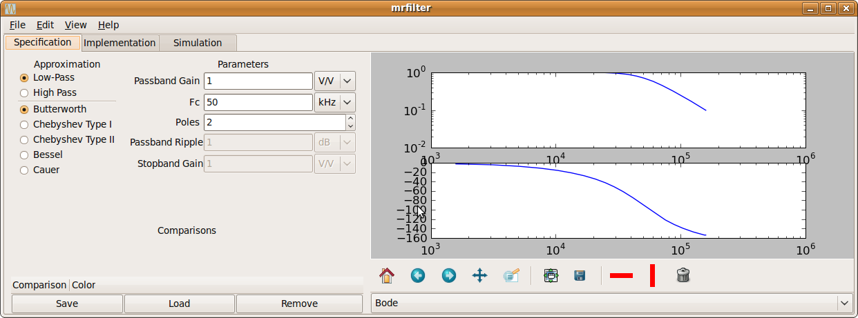
The Mr. Filter specification tab contains the following areas:
- Approximation area
Used to select the filter type and shape.
- Parameters area
Used to set the filter's detailed numeric properties
- Plot area
Plots filter data in different forms. By default a Bode plot is shown.
- Comparisons area
You can store multiple filters for side-by-side comparison. Use the comparison area to load or remove saved filters.
The general design procedure for active filters is the same whether or not you are using Mr. Filter. Figure 2, “General filter design procedure” shows the general procedure.
The first step, as is always the case in engineering, is to define the problem. Which frequencies do you want to retain and which do you want to reject? By how much do you need to reject those frequencies? Are there any other requirements, such as flatness of the passband or linearity of the phase response? Once you have defined the problem, you can choose the shape of filter you need (low-pass, band-pass, etc), the passband gain, and perhaps the filter polynomial (Butterworth, Bessel, etc).
Next you must choose the filter's parameters. There is some leeway here. Every parameter has tradeoffs. Pick the polynomial, cutoff frequency, number of poles, and ripple (if applicable). Use the fewest number of poles that satisfies your requirements. Keep tweaking the parameters until the requirements are satisfied.
This done, the next step is to choose a circuit topology. With few exceptions, any topology can implement any filter, but there is a tradeoff between the component count, adjustability, and stability in the face of component variation. Once you've chosen a topology, calculate all the component values. If you are using Mr. Filter, you need only choose a few seed values and the program will calculate the rest.
The next step is important, but often overlooked. Real components deviate from their nominal value, and different circuits have different sensitivities to these variations. A circuit with a high sensitivity to a particular component will have a large change in behavior in response to a small change in that component's value. If your circuit's sensitivities are too high, you must either pick a different topology or use components of tighter tolerance.
Next you must choose an op-amp. Up to this point, all calculations have assumed an ideal op-amp. But real chips have imperfections: finite open-loop gain, finite input impedance, and finite bandwidth are the most important.
The final step is simulation. Use spice or another tool to simulate your circuit to verify that your calculations were correct and the chosen op-amp will be adequate. If the simulation results closely match your predictions, then your filter design is complete. If not, recheck your calculations or choose a different op-amp.
Mr. Filter is designed to follow this general procedure. Requirements
definition is beyond the scope of the program; the user should start
Mr. Filter already knowing his requirements. So the first step in using
Mr. Filter is to select the filter's shape, polynomial, and parameters.
As you do this, the plot will update continously. By default it shows
a Bode plot, but step response, impulse response, and pole-zero plots
are also available. To assist in choosing the parameters, you can
save several filters for comparison, plotting them against each other.
You can also place markers on the plot using the
 and
and
 buttons.
These markers will remain in place through pan and scale operations
until you remove them with the Trash button.
buttons.
These markers will remain in place through pan and scale operations
until you remove them with the Trash button.
Once satisfied with your filter's transfer function, proceed to the tab of the program. First select the topology you desire. A schematic of your circuit will appear. Next select the component tolerance that you will use.
Note
As of version 0.2.1 only Ideal components are supported.
. Then you must choose a few seed values for your circuit. The rest of the components will be calculated based on these seeds. Choose seeds that produce convenient component values.
Finally, navigate to the tab. First you will probably want to simulate component spread to see the effect of circuit sensitivity. Check either 'Corner Case' or 'Monte Carlo' from the drop down menu. Monte Carlo analysis will randomly change the value of each component within its assigned tolerance and plot the result. It is a very useful technique and it scales well to larger circuits. Corner Case analysis will simulate the circuit alternately setting each component to its minimum and maximum value, based on the component's tolerance. The result will be more conservative than Monte Carlo analysis, but at the cost of longer run times for large circuits.
You can also simulate your circuit using a real opamp model instead of an ideal opamp. Just choose a model file from the Op-Amp file chooser. Mr. Filter does not ship with any models; you must make or download your own. Manufacturer's websites are a good place to get models. The Mr. Filter website has a list of models that are known to work. You should use the Gnucap simulation engine when using a real opamp.
- What are sensitivities?
In general, the sensitivity of Y with respect to X is the percentage change of Y divided by the corresponding percentage change of X. That is, if R1 changes by 1% and the circuit's Q changes by 5%, then the sensitivity of Q with respect to R1, denoted
- What opamp models work with Mr. Filter?
This will depend on what simulation backend you are using. For Gnucap, a number of opamp models have been tested. The Mr. Filter website has a compatibility chart. Spicelib includes many opamp models that have been tested with ngspice. Spicelib automates the process of downloading models from multiple vendors, testing them, and presenting them to gEDA.
Version 0.2.1 is an early release. Bugs are many and features are few. Here is an incomplete list:
There are no schematics for state-variable or high-pass tow-thomas filters.
Tow-thomas, state-variable, and multiple-feedback filters are unimplemented.
Band-pass, band-stop, and all-pass filter shapes are completely absent.
Chebyshev type II and Cauer filters do not work correctly.
Mr. Filter was written by Alan Somers
(<asomSPOOONers@users.sourceforge.net> Remove the utensil).
To find more information about Mr. Filter, please visit the
Mr. Filter Web
page.
To report a bug or make a suggestion regarding the Mr. Filter application or this manual, send an email to mrfilter-users@lists.sourceforge.net or post a bug at http://sourceforge.net/projects/mrfilter/
This program is distributed under the terms of the GNU General Public license as published by the Free Software Foundation; either version 3 of the License, or (at your option) any later version. A copy of this license can be found at this link, or in the file COPYING included with the source code of this program.